LIAO 3rd Edition PEARSON EDUCATION PUBLICATIONS. In this set of notes we examine filter design using transmission Lines.

Microwave Filter
In this project design and simulation of.

. Design of Microwave Filters The first step in the design of microwave filters is to select a suitable approximation of the prototype model based on the specifications. Coupled Line and Tunable Band Pass Filters. Microwave Engineering 2.
ELEC 412 RF Microwave Engineering Fall 2004 Lecture 11 RF Filter Design Basic Filter Types Filter Attenuation Profiles RF Filter Parameters Insertion Loss. This design method is based stric tly on using small -signal S -parameters for the design of M1 the input matching circuit and M2 the output matching circuit. Microstrip Realization Transformation from LPF to other Filters.
Microwave Filters - IV. MICROWAVE AND RADAR ENGINEERING By M. In this thesis ultra-wideband UWB microwave filters and design challenges are studied anda microstrip UWB filter prototype design is presented.
The necessary electromagnetic spectrums at work in RF and microwave designs make RF filters have to be that much more exact in their applications. Design and Implementation of RF and Microwave Filters Using Transmission Lines Rethabile Khutlang A thesis submitted to the Department of Electrical Engineering. Design a LC bandpass filter.
Designing a high -power microwave amplifier that is illustrated in the book Microwave Circuit Design Using Linear and Nonlinear Techniques by Vendelin Pavio and Rohde. Center frequency f03 GHz Pass Band fh 3268 GHz fl 2712 GHz Bandwidth 20 Insertion Loss 4 dB within the given band Fig -3. The emphasis is on design at.
Transformations are then applied to convert the prototype designs to the desired frequency range and impedance level. MICROWAVE FILTERS DESIGN - PowerPoint PPT Presentation. The example mentioned here is for micro-strip based LP filter.
KULKARNI 4th Edition UMESH PUBLICATION 2. Remove this presentation Flag as Inappropriate I Dont Like This I like this Remember as a Favorite. Butterworth Bandpass Filter Design Bandpass Filter is to be designed with a N 3 b 3 dB passband ripple c 15 GHz center frequency and meet a bandwidth requirement of 200 MHz.
49 89 2420 828 198 Email. Apply impedance scaling step 3. RF filter design especially in 5g wireless networks faces stress from the advancement of MIMO technology and its application with phased array technology.
40 dB at 2Fc. The design is simplified by beginning with low-pass filter prototypes that are normalized in terms of impedance and frequency. Replace inductances and capacitances with equivalent λ8 transmission lines.
It should have a cutoff frequency of 1 GHz. Design filters with a completely specified frequency response. Filter Design and Tuning using CST Studio Suite Franz Hirtenfelder Applications Engineer CST Branch Office Munich Elsenheimer Strasse 55 D-80687 München Munich Germany Tel.
Extensive treatment of scattering parameters that naturally describe power flow and of Smith-chart-based design procedures prepare the student for success. Distributed Filter Implementation Design a 4th-order low-pass standard maximally flat 3 dB Butterworth filter. Fundamentals of Microwave and RF Design enables mastery of the essential concepts required to cross the barriers to a successful career in microwave and RF design.
LAω 10log 10. The UWB bandpass filter operating in the 36 GHz to 106 GHz frequency band is targeted to comply with the FCC spectral mask for UWB systems. We start with a lumped-element design.
RF CIRCUIT DESIGN THEORY AND APPLICATIONS By REINHOLD LUDWIG PAVEL BRETCHKO 2 nd Edition. View by Category Toggle navigation. 50 Ohm Cutoff frequency Fc.
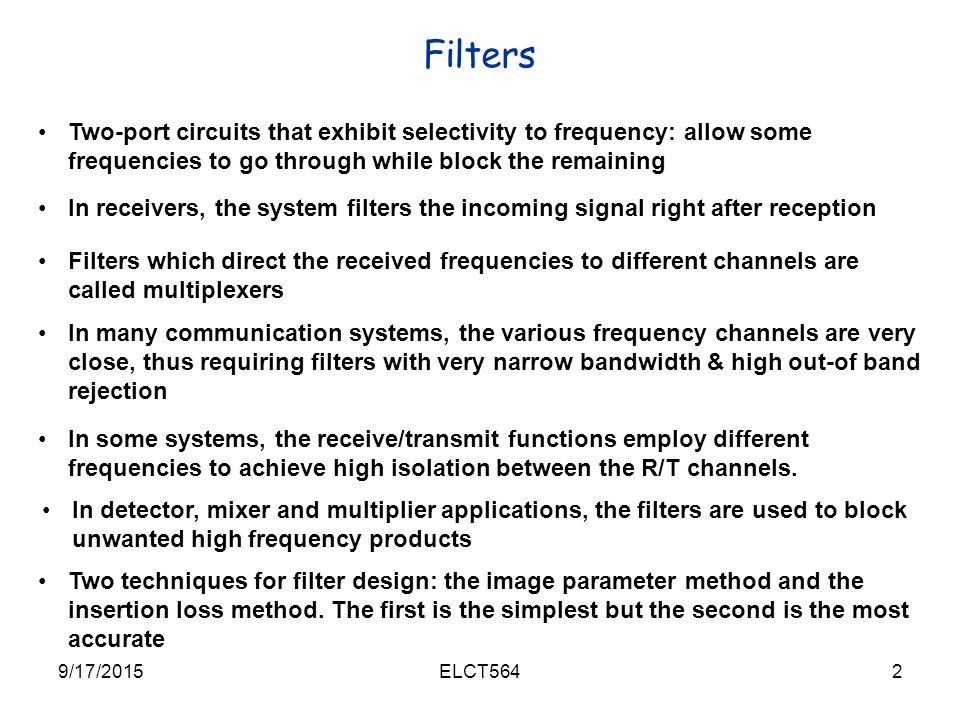
Microwave filters perform the same function as electric filters at lower frequencies but differ in their. Lecture 22. Microwave Filters - V.
MICROWAVE DEVICES AND CIRCUITS By -SAMUEL Y. Calculate the order of the filter from the necessary roll off as per the given specifications. Out Thus by conservation of energy.
Microwave Filters - III. Select the normalized filter order and parameters to meet the design criteria. From the element values of lowpass prototype step 2.
1 38 Actions. The science is developing the mathematical procedure to go from the mathematical specification of the desired response to the final microstrip realization. Elements what you need in a low-pass design.
The filter converted to heat or is reflected P r at the input port. We can use low and high impedance lines to approximate lumped elements. PPPinc r out which alternatively can be written as.
Apply bandpass transformation using J-inverters Step 4. PPP P inc r out abs Now ideally a microwave filter is lossless therefore P abs 0 and. Filter design as with most RF design is a combination of art and science.
Scattering parameters vs frequency Conclusion. The lectures would try to emphasize on the need to understand the key concepts behind a microwave filter or amplifier design so that the students themselves can design a. 49 89 2420 828 101 Mob.
Filter design Example Design 5-poles low pass filter with a cutoff frequency of 2 GHz impedance 50 Ohms insertion loss 15 dB at 3 GHz g1 0618 g 2 1618 g3 2 g 4 1618 g 5 0618 Maximally flat response 37 EM Wave Lab. EE433-08 Planer Microwave Circuit Design Notes i A Brief Introduction To Microwave Engineering and To EE 433 The microwave region is typically defined as those frequencies between 300 MHz and 300 GHz. Microstrip Band Pass Filter is designed and simulated successfully on AWR DE Microwave office software Results obtained are as follows.
A two-port component used to provide frequency selectivity in satellite and mobile communications radar electronic warfare metrology and remote-sensing systems operating at microwave frequencies 1 GHz and above. The art is identifying the structures that intrinsically have the desired response. D 50 Ω characteristic input impedance Find the inductive L and capacitive C elements.
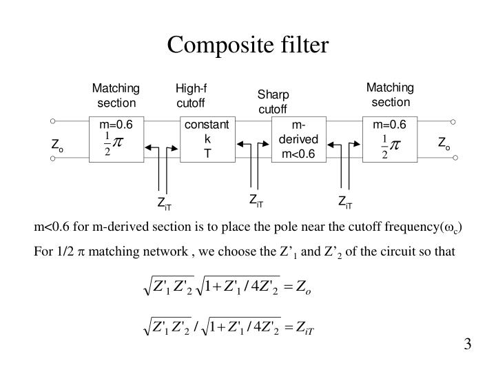
The prototype filter is composed of quarter-. Recall 1 MHz 1x10⁶ Hz and 1 GHz 1x10⁹ Hz These frequencies include free-space wavelengths between 1 m and 1 mm. 49 170 9160 110 Fax.
Microwave Filters - II. Low Pass Chebyshev Filters. 5 ECE-601 4 l-a.
The course will introduce design principles of RF and microwave filters and amplifiers. The f0 is 28 GHz bandwidth is 500 MHz and the input and output impedance 50. The order can be calculated as follows.
1 inc r out inc inc rout inc inc PPP PP PP PP Filter P inc P P r P abs. To illustrate RF filter design we will take RF Low Pass Filter with the following specifications. Filter Design Using Transmission Lines.
This article describes basic steps in microwave and RF filter design. The example mentioned here is for micro-strip based LP filter.
Elct564 Spring 17 20151elct564 Chapter 8 Microwave Filters Ppt Download
Ppt Microwave Filter Design Powerpoint Presentation Free Download Id 332301
Ppt Microwave Filter Design Powerpoint Presentation Free Download Id 332301
Design Of Rf And Microwave Filters Ppt Video Online Download

Design Of Rf And Microwave Filters Ppt Video Online Download
Design Of Rf And Microwave Filters Ppt Video Online Download

Ppt Microwave Filters Design Powerpoint Presentation Free To View Id 44c5d9 Mti2z

3 Design Of Rf And Microwave Filters Pdf Low Pass Filter Filter Signal Processing
0 comments
Post a Comment